How to Read Steel Structural Drawings

Reading a structural drawing can be challenging, especially if you are starting your Structural Engineering Career. All you see at a glance are complex lines, texts, and arrows. Sometimes, you feel like you are falling behind other Engineers if you cannot read the structural drawings correctly. However, reading these drawings may be less challenging if you understand the basics.
Below is an outline discussing structural drawings and how to read them.
What Does Structural Drawing Mean?
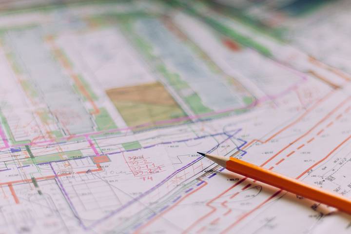
A structural drawing is a detailed plan elaborating how to construct an industrial plant, a building, or a factory. It is like a road map providing guidelines on the construction process. Sometimes, Engineers derive structural drawings from architectural drawings.
Steel shop drawings display the connections of materials in a construction. It guides builders in selecting which materials to use. Ideally, the steel structure illustration shows the exact position of every building material.
Structural Symbols, Tagging, and Abbreviations

When dealing with structural drawings, you will encounter some tags and symbols you may not be familiar with, especially if it is your first time reading them. So, it would help to acquaint yourself with these symbols before you can start reading.
Still, there is no need to freak out. Most tags, symbols, and abbreviations are found on the drawing’s first sheet or cover. Thus, you can refer to the first page if you do not understand any symbol or tag. You will likely encounter the following tags and symbols in a structural steel drawing.
- RENF/RFT-reinforcement.
- U.N.O- unless noted otherwise.
- THK-thickness.
- T.O.C-top of concrete.
- E.J.- expansion joint.
- G.L- Gate level.
- F.F.L- floor finish level.
- S.S.L- structural slab level.
- C/C- center to center.
- NTS- not to scale.
- TYP-Typical.
Point Out Callout Symbols

A callout symbol is a unique type of symbol that needs special mention. Engineers draw your attention to specific areas of the drawing. These are icons, and you can find them mainly on the drawing’s margins.
When they direct your eyes to a particular area of the drawing, it is to provide more details concerning the construction. For instance, an engineer can use a callout symbol to show where two steel bars should meet.
General Structural Steel Note Sheet

The general structural note sheet is often the cover page or the first page of the structural drawing. It shows the compressive or yield strength of the materials the contractors will need to finish the construction.
The details can include the characteristics of the concrete, the steel or reinforcement bars required, and the standard rebar bends or hooks. Also, lap splicing standards and a construction summary showing the specifications and procedures to follow during the construction are part of the General structural steel note sheet.
It comprises a general summary of the overall standards of the construction and how to execute a particular project. It highlights details on the criteria of the design and the considerations the Engineer used in the structural design, such as the code standards, load consideration, soil bearing capacity of the foundation, and much more.
Typical Details

The general typical details sheet contains all the information on the arrangements of reinforcements, such as the details of bending bars in the slab and beam, typical shear walls, and maintaining wall details. It lays down all the necessary information the contractor will need to start and complete the construction project.
In addition, you can find details about laying and building a masonry wall and its standards in this sheet. The good thing is that it is precise, straightforward, self-explanatory, and easy to understand.
Thus, whenever you get confused or unsure how to handle a certain detail, you only need to consult the typical details sheet. Read, review, and understand every section before executing any project.
Learn the Working of the Scales
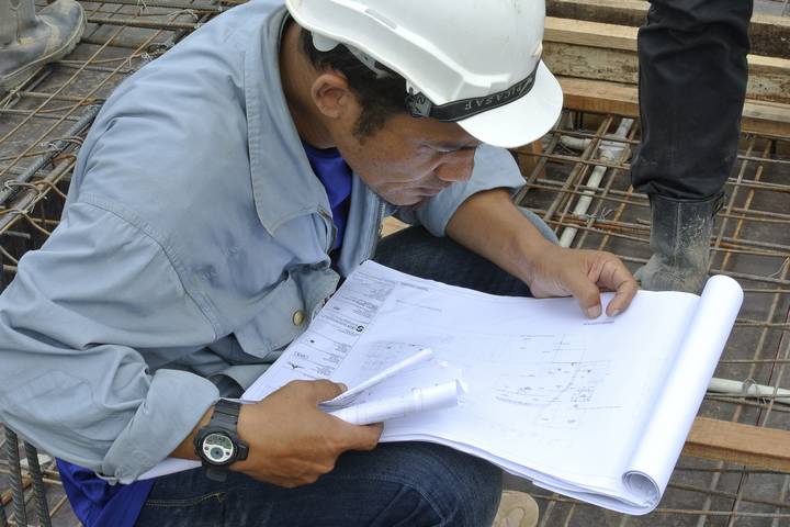
The scale is a ratio you will find on the sheet to represent actual dimensions on the ground. Ideally, every measurement unit on the sheet depicts a larger distance on the ground. The scales show how small or big structures will be after construction. Many engineers prefer to use inches/foot to represent the dimensions of their scales.
Scales vary, and sometimes, they can be somehow confusing to newbies. Still, you can find more than one scale in a drawing. So, you must be keen when translating the scales. Otherwise, the structure may not turn out as expected. Interpreting scales correctly requires you first to understand what type they are. If you are not sure, ask the Engineer.
Additionally, you may need a scaled ruler or architectural scale since it can interpret the scale for you, even when there is more than one depiction in the drawing.
Identify Circled Numbers

A circled number flags the information on that page to indicate more details on the same topic in a separate part of the drawing. For example, the scales used can be so small that the Engineer cannot elaborate it here. A circled number will draw your attention to the area with further details.
Reading steel structural drawings can be complicated yet fun if you understand the specifics. The details may seem too much and overwhelming, but only because it is a theory. You can read structural drawings like a pro with this guideline and practice.


